Hydraulic gear pumps convert the mechanical energy provided into hydraulic energy. A distinction is made between internal and external gear pumps.
Content
Internal Gear Pumps - Quiet and Efficient
Internal gear pumps are particularly quiet, which is the most outstanding feature of this type of pump. Their area of application is therefore primarily used in stationary hydraulics (presses, plastics machines, machine tools, etc.). They are also used in vehicles that work in closed rooms (e.g. electric forklifts).
How does a hydraulic internal gear pump work
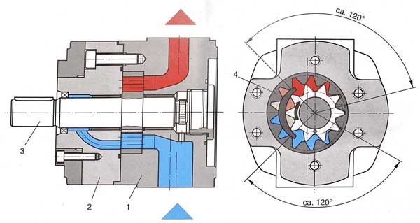
Abb.1 Innenzahnradpumpe, Bosch Hydrauliktrainer Band 1
The toothed rotor is connected to the drive machine via the shaft. The volume between the tooth flanks increases as the toothed rotor and ring gear rotate. This sucks in the hydraulic fluid.
The increase in volume takes place at a rotation angle of 120°, which means that the displacement chamber does not fill suddenly, but relatively slowly. Due to the slow opening, the running smoothness is particularly high and the suction behavior is very good.
External gear pumps - The most common design
External gear pumps are hydraulic pumps that are produced in the largest quantities. The reasons for this are diverse:
High pressure range (up to 300 bar) with relatively low weight
Low price
Large speed range
Can be used in a large temperature and viscosity range
How does an external gear pump work?
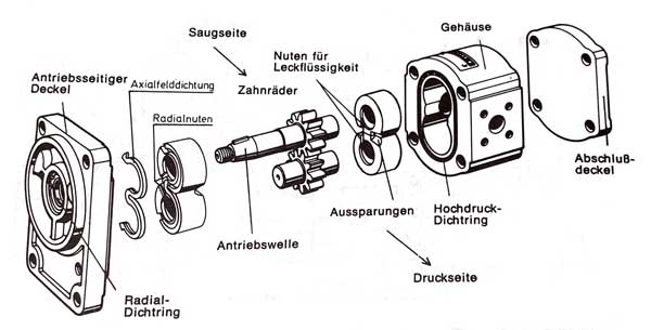
In terms of structure, the external gear pump is the simplest solution.
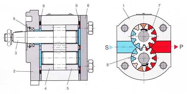
The upper gear (No. 7) is connected to the drive unit (electric motor, combustion engine, PTO gear, etc.) via the drive shaft and a clutch (eg dog clutch or gear clutch).
Both gears (7 and 8) are positioned by the bearing brackets (also known as bracket flanges) in such a way that the gears mesh (mesh) with minimal play during rotation. The displacement chambers are formed between the tooth flanks, the housing (inner wall) and the end faces of the bearing brackets.
The liquid volume enclosed in a tooth gap is conveyed by the rotation of the gear from the suction side “S” and the pressure side “P”, displaced at the point of engagement of the gears and pressed into the pressure port. For simplification, the pressure increase from the suction side to the pressure side can be assumed to be linear. As a result of this linear pressure distribution, high shaft and bearing loads occur. The geometric displacement volume is constant.
In hydraulic gear pumps , leakage oil flows are caused by the clearance between the gear and the housing. To ensure that only very little liquid gets through this gap from the pressure side to the suction side as the pressure increases, the cover-side bearing bracket is pressed against the end faces of the gear wheels via an axial pressure field. This is also referred to as pressure compensation. Efficiencies of 0.8 to 0.9 can be achieved.
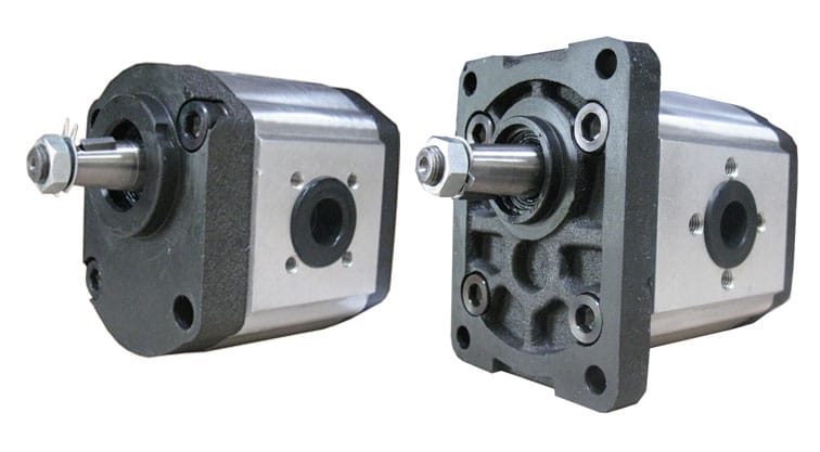
Gear Pumps - Application
Typical areas of application for gear pumps are construction machinery, agricultural machinery, tractors, hydraulic units. Gear pumps are also frequently used in wood splitting machines, especially in connection with PTO drives.
The most common aluminum pump series are group 0.5, 1, 2, 3 and 4
Gear pumps can be combined to 2-fold or 3-fold pumps, different assemblies are possible, e.g. combination group 3 with group 2, or BG2 with BG1 etc.
Calculate delivery volume of a defective gear pump | formula
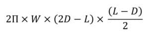
It happens again and again…The gear pump stops performing and removes it from its tractor or power unit. Desperately you look for the type plate so that you know exactly where you can get the corresponding spare part. The only stupid thing is if the type plate is missing and there is no indication of the displacement of the pump. There is a relatively simple way of determining the displacement of a gear pump after disassembly using the following formula:
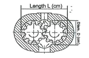
The dimension “W” is the width of the gear, L is the width of the gear pair, “D” is the diameter of a gear. All dimensions are given in cm in order to obtain the delivery volume in cm3/rev directly.
After determining the dimensions W, D and L, the displacement of the pump can be calculated using the formula above.
Reversal of the direction of rotation of a gear pump
In some practical cases it is necessary to reverse the direction of rotation of a gear pump . Example: You have operated a clockwise pump with a gearbox on a rear PTO and now want to operate the unit on a front PTO. The direction of pump rotation must then be changed from right to left.
The direction of rotation is usually indicated by an arrow on the housing. To indicate the direction of rotation, look at the shaft from the front:
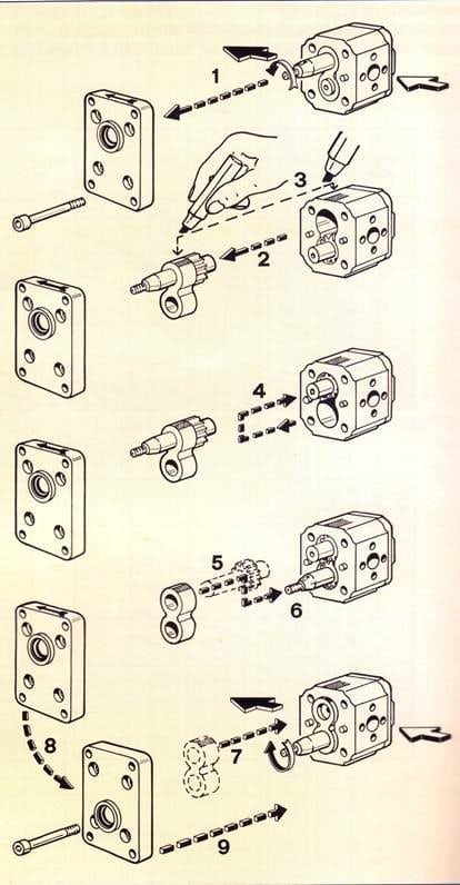
The direction of rotation is reversed according to the following instructions:
Cleanliness must be ensured both during disassembly and assembly of the gear pump . If seals are damaged during assembly work, they must be replaced immediately with new seals. In addition, when assembling the gear pump, make sure that the seals are not pinched. The tightening torques of the housing screws must be observed.
A video on reversing the direction of rotation of a gear pump can be found here:
Gear pump for car trailers - how does it work?
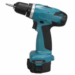
The question keeps coming up: Can a gear pump be operated with a cordless screwdriver ? The answer is simple: yes, it is possible.
As a rule, hydraulic gear pumps of group 1 with a displacement of 3 – 3.5 cm³/rev are used. The drive of the cordless drill with 18 volts and around 41 amps develops an output of around 750 watts or a torque of between 40 and 50 Nm (depending on the manufacturer). The output speed of the cordless screwdriver is approx. 1000 rpm in level 2.
This gives the displacement of the pump:
With a drive power of 0.75 kW, the maximum pressure is:
This makes it easy to drive hydraulic pumps with a cordless screwdriver.
A typical application is the conversion of a hydraulically tiltable trailer using a hand pump. The hand pump is replaced by a gear pump and powered by a cordless screwdriver . There are a few points to consider when converting. If you have any questions, please contact us.
Click here for the gear pumps in our hydraulic shop!
In our webshop you will find a large selection of hydraulic gear pumps.