Hydraulic lowering brake valves - safety device in hydraulic systems
Counterbalance valves are hydraulic valves consisting of pilot-operated check valves and associated throttling and damping devices. These chokes are usually pressure relief valves with a defined open-loop control ratio.
Lowering brake valves in the hydraulics make it possible to regulate the lowering speed according to the volume flow supplied on the other side of the consumer.
Content
Hydraulic lowering brake valves are used when pulling loads need to be held safely and moved in a controlled manner. This is done by setting the valve to a higher pressure than the preloaded pressure, which corresponds to the maximum permissible load.
What are pulling loads in hydraulics?
Pulling loads occur, for example, with hydraulic winches. Suppose you want to pull a felled log up a slope in the forest. If you stop the hydraulics halfway, the tree pulls on the winch due to the downhill force. Without a hydraulic lowering brake valve, the tree would roll uncontrollably down the hill and irreparably damage the drive motor of the winch.
In addition to lowering brake valves, hydraulically released multi-disc brakes are also used in hydraulic winches. These hold the load securely when the hydraulic system is switched off. A hydraulic motor is usually not enough to hold a pulling load because there is no self-locking.
Hydraulic lowering brake valves are safety valves
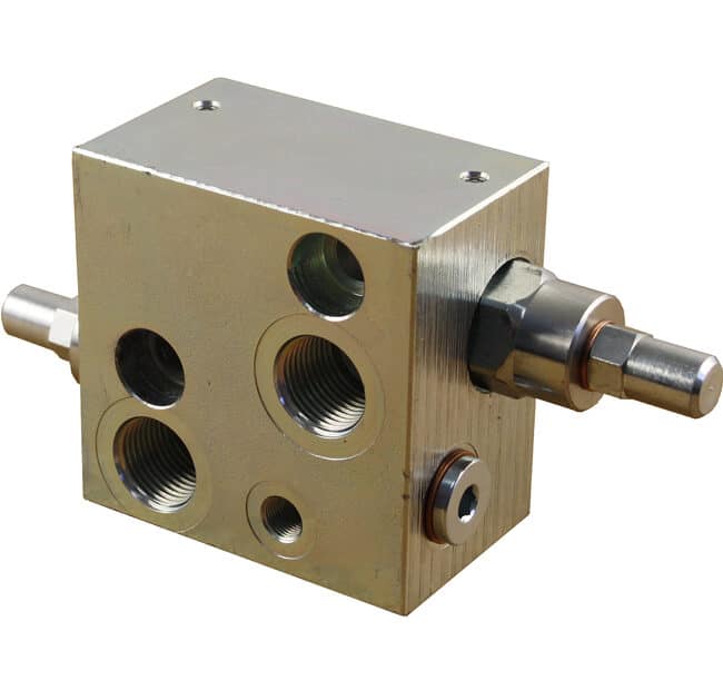
Counterbalance valves are often used as safety valves. This means that these valves must be rigidly connected to the consumer (directly flanged). Mounting by means of hydraulic hoses is not permitted. If a hydraulic hose bursts, the safety function of the lowering brake valve would be cancelled.
Lowering brake valves for hydraulic motors
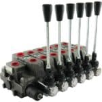
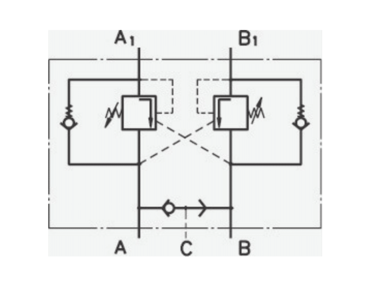
As already mentioned, lowering brake valves are usually used in combination with a hydraulically released multi-disc brake. Therefore, the lowering brake valves for hydraulic motors have an additional port “C”, there the connection to the brake is made. For the common engine series, especially for gerotor engines, counterbalance valves are available for one and for two engine directions of rotation(single-acting and double-acting counterbalance valve).
Lowering brake valves for hydraulic cylinders
For hydraulic cylinders, a distinction is made between pure load holding valves and lowering brake holding valves. Pure load holding valves are usually designed as hydraulically releasable check valves and only have the task of holding a cylinder load (e.g. on vehicle lifting platforms). If the check valve is unlocked when the control valve of the hydraulic system is actuated, the cylinder retracts without braking. If there is a large load on the cylinder, retraction can be dangerous.
In such a case, the use of a lowering brake holding valve is recommended. This valve type includes both a hydraulically pilot-operated check valve and a counterbalance valve.
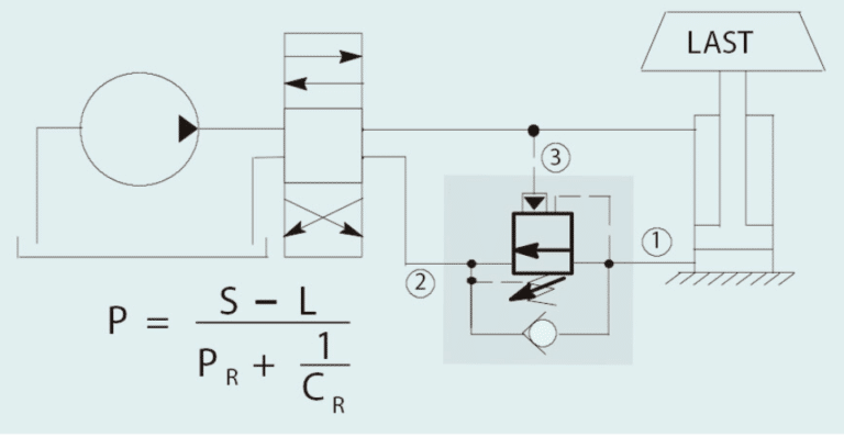
Hydraulics lowering brake valve - open ratio
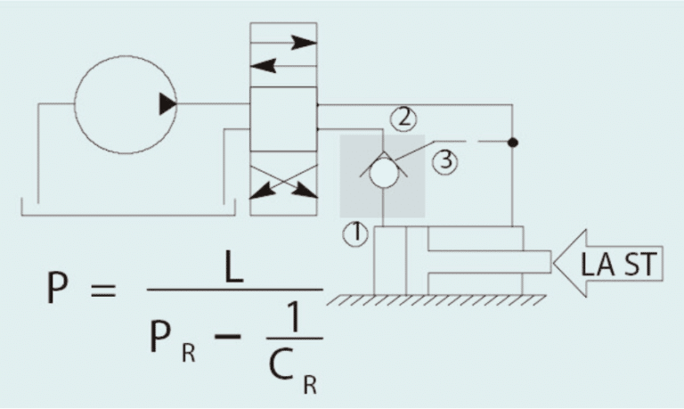
The ratio between the lift surface and the pressure boundary surface is called the lift ratio. The lift ratio can be calculated by dividing the lift area by the pressure boundary area.
For example, a common open ratio for hydraulic motor lowering brake valves is 4.5:1. If now the pressure setting of the valve is 210 bar and the load is 140 bar, then the required upstream pressure is (210 bar – 140 bar) / 4.5 = 15.56 bar.
In general, lower open-loop ratios provide more accurate and stable motion control, especially for “unstable” drives with large loads. However, larger lift ratios can improve the efficiency of hydraulic drives, resulting in lower heat generation. However, a higher drive-up ratio can also have negative effects on the stability and accuracy of motion control.
For hydraulic motors, counterbalance valves with a slightly larger open ratio are usually used. For loads to be held, it is strongly recommended to use a hydraulically released multi-disk brake in addition to the hydraulic motor. Hydraulic motors do NOT have self-locking and are therefore not suitable for holding loads.
Set hydraulic lowering brake valve correctly - Explanation in 6 steps
In order for lowering brake valves to function correctly, they must be properly adjusted. The setting should be at least 1.3 times the expected load pressure, as counterbalance valves are considered a safety device. Therefore, only trained personnel may perform the setting!
Correct adjustment can be performed in the hydraulic system in six steps. We explain the adjustment process using the example of a hydraulic cylinder:
- Adjust the counterbalance valve to the maximum pressure, observing the direction of rotation of the adjusting screw according to the manufacturer’s instructions.
- Raise the load a few millimeters using the hydraulic system to avoid injury during the adjustment process. If the load is lifted too far, there is a risk of injury to the installer.
- Switch off the hydraulic system. The lowering brake valve must not be pressurized with the control pressure during the adjustment process. The position of the hydraulic cylinder should be marked with a waterproof pen or similar.
- For the time being, set the hydraulic lowering brake valve exactly to the load pressure. To do this, gradually reduce the pressure setting on the valve ( observing the direction of rotation of the adjusting screw). As soon as the piston rod of the cylinder moves, the pressure setting is increased again until the load stops again. If the pressure setting is reduced too quickly, the load will drop abruptly, which can damage the mechanics if multiple cylinders are used. The pressure setting in the lowering brake valve increases proportionally to the spring preload (approximately linear increase). Therefore, the preload can be increased by one third when adjusting to the load pressure. To do this, first count the revolutions of the valve required to keep the load straight. Please note that the load must be secured against unintentional lowering beforehand.
- Then open the valve completely (minimum pressure setting), counting the revolutions accurately. Then re-tighten the adjustment screw by the previously counted turns and add 30% to achieve the desired safety level of 1.3 times the load pressure. Example: It takes 5 revolutions to hold the load. It then takes 5 + 30% = 6.5 revolutions to achieve 1.3 times the load pressure.
- Finally, the adjusting screw must be secured against unauthorized adjustment. This can be done by sealing with a lead seal or by using threadlocking varnish.
Buy Hydraulic Counterbalance Valves in our store
In our hydraulics store you will find a wide range of counterbalance valves. Visit us and benefit from our extensive product portfolio.
- Mobile control block - 13. May 2023
- Hydraulics lowering brake valves - 6. May 2023
- axial piston engines - 2. May 2023